

An engineer can make a drawing look safer by tightening a tolerance. It may also make the part harder to manufacture, slower to inspect, and more expensive—without improving the function that matters. The better question is not “How tight can we make it?” but “What variation can the product tolerate while doing its job?”
I encountered this kind of tradeoff while doing orthopedic-device engineering at Hospital for Special Surgery, where geometry, fit, manufacturing methods, and inspection all had to be considered together. The specific example below is hypothetical; the point is a decision method that travels well beyond medical devices.
Begin with the functional relationship
Imagine a reusable instrument with two mating parts. The user needs a mechanism that engages reliably and feels consistent. A dimension on one component matters only because of how it relates to the other component, its assembly, and the range of use conditions. If the team starts by copying a tight number from an earlier drawing, it may miss the functional relationship entirely.
Geometric dimensioning and tolerancing (GD&T) provides a shared language for communicating design intent. ASME Y14.5-2018 (R2024) establishes symbols, rules, and definitions for stating and interpreting geometric requirements. The standard is not a substitute for choosing the right functional requirement. It helps teams express that requirement consistently once they understand it.
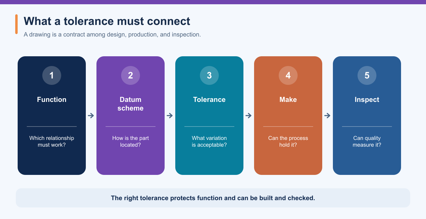
Put the datum conversation in the room early
A datum scheme is not decorative notation. It tells people how to orient and locate a part for a specified requirement. If design imagines one functional reference, manufacturing fixtures the part from another, and quality measures it from a third, everybody can be busy and still disagree on whether the part is acceptable.
The review should ask what locates the part in its actual assembly or use, which features matter to performance, and how the part will be held for production and inspection. The answers may change the drawing, the fixture, or both. This is the moment when a short cross-functional discussion can prevent a long series of deviations.
| Function asks | Manufacturing asks | Quality asks |
|---|---|---|
| Which fit or movement must be protected? | Can the process hold the specified relationship? | Can we measure that relationship repeatably? |
| Which features locate the part in use? | Can the part be fixtured from those features? | Does the inspection setup reflect the intended datums? |
| What variation is acceptable? | What variation does the process actually produce? | Are acceptance criteria unambiguous? |
No function should be expected to answer alone. A drawing can be technically sophisticated and still be a poor contract if it cannot be built or measured in a way that reflects intended use.
Make the tolerance stack visible
The part that matters to the user is often an assembly, not an isolated feature. Several individually acceptable variations can combine to create an unacceptable fit or feel. A tolerance stack-up is one way to see that interaction before the first difficult build.
The analysis should be honest about assumptions: which dimensions vary independently, which are controlled by the same setup, and what assembly or process adjustment is allowed? A neat worst-case or statistical result is useful only if its model matches production reality. The team may discover that one feature needs better control while another can be relaxed.
For medical devices, these decisions also connect to design inputs, verification, and transfer into production. For other products, the regulatory records differ, but the underlying handoff is the same: the product must be buildable and inspectable as designed.
A better drawing review
Before release, I would ask the designer to explain the functional purpose of each critical control in plain language. Then I would ask manufacturing how it will make it, quality how it will inspect it, and the program team which lead times or tooling dependencies it creates. If one answer is uncertain, the drawing is not yet done communicating.
The goal is not the fewest symbols or the tightest numbers. It is a shared definition that lets different people make interchangeable parts with confidence.
The same traceability challenge appears in Design Input vs. Design Output: a functional need has to become a specification the team can build and verify. For an example of analysis informing a decision before a drawing is finalized, read What FEA Taught Me About Better Orthopedic Design Decisions.
If your team is working through a difficult interface between design, manufacturing, and inspection, reach out. I would welcome a conversation about the functional question behind the tolerance.

Leave a Reply